|
Fuselage:
1. Cut a 30" section of gutter pipe for the fuselage. A table saw or Dremel® with a cutting wheel works good for
this. The Dagger has no down thrust or right thrust.
2.
Cut out the lower rear fuselage as shown on drawing #1. DO NOT THROW THE SCRAP AWAY, use it
to make other PVC parts!
3. You will be installing the wing hold down dowels and cutting the radio
access hole at FINAL ASSEMBLY, after
proper CG is determined.
Tail:
1. Cut the one piece horizontal stab/elevator and the vertical fin from Coroplast® as shown on drawing #5. Use
a good sharp razor or X-acto knife.
2. Hinge the elevator by cutting away one side of a Coroplast® corrugation. A box opener type knife or razor
wrapped in masking tape with just the tip exposed works good for this.
Tail attachment:
1. Fabricate two PVC tail mounting "L" brackets as shown on drawing #5 (Sheet metal shears
work good for cutting
PVC)
2. Trim forward edge of "L" brackets to contour of vertical fin.
3. Drill 3 evenly spaced 1/16" holes in each "L" brackets for vertical
fin screws. Enlarge holes in ONE SIDE ONLY
to 1/8"
4. Attach "L" brackets to vertical fin with #6 x 1/2" self-tapping screws. (CA can be used to tack parts together
while installing screws)
5. Drill 3 evenly spaced 1/16" holes in each "L" bracket for horizontal stab attachment.
6. Use the "L" brackets/vertical fin assembly as a
template to mark and drill 1/16" tail attachment holes in
fuselage. PROPER CENTERING OF TAIL TO FUSELAGE IS CRITICAL TO YOUR PLANES PERFORMANCE.
7. Enlarge holes in "L" BRACKETS ONLY, to 1/8"
8. Attach vertical fin, and horizontal stab/elevator to fuselage using #6 x 1/2" self-tapping screws.
Power pack:
1. Fabricate a
firewall from 3/4" plywood. We like to "step" our firewalls for greater impact strength (as shown
on power pack top view drawing). Mounting it flush with the forward edge of the fuselage
works fine also (as
shown on the power pack side view)
2. Cut a groove, centered, at the bottom of the firewall, and CA a 1" yardstick standoff in place.
3. CA the power pack
yardstick to the 1" standoff, and CA the middle and aft 1" yardstick standoffs in place.
Placement of the middle standoff is not critical, BUT IT MUST NOT INTERFERE WITH RADIO GEAR.
4.
CA a piece of PVC scrap to the power pack yard stick directly above the middle standoff. This is for added
mount screw grip.
5. Fabricate a PVC switch mount bracket (Size will be determined by
your switch), and CA to Power pack yard stick
directly above rear standoff.
6. Using power pack assembly as a guide, mark approximate locations of middle and aft standoffs on the outside
bottom of the fuselage. Install power pack into fuselage and drill 1/16" holes through fuselage, and power
pack, at middle and aft standoff locations. Remove power pack from
fuselage and enlarge holes IN FUSELAGE
ONLY to 1/8"
Wing:
1. The wing is laid out on a 2' x 4' piece of Coroplast® with the corrugations running CHORDWISE (as shown on
drawing #6). It is acceptable to build this wing from two 2' x 2' Coroplast® pieces butted up against at the
wing center line.
2. Mark all fold lines, spar lines, and wing tips on the Coroplast®.
3. Cut Coroplast® material away from the outside edges of the bottom panel wing tips.
4. Cut the top wing centerline, to the leading edge fold line ONLY!
NOTE: This is done to facilitate folding half of the wing at one time, making assembly much easier. If you are
building your wing from two separate pieces, this will already be done.
5. Cut two 2 1/2" x 20" pieces of Coroplast® with corrugations running LENGTHWISE for ailerons. Refer
to
drawing 3, and mark the hinge line, and notch the outboard edge 1/4", forward of the hinge line only (this is
for wing tip folding clearance).
6.
Hinge the ailerons by cutting away the BOTTOM portion of one corrugation, forward of the hinge line as shown
in drawing #6.
NOTE: If the hinge seems a bit
stiff (Coroplast® varies), you can cut out two flutes and that should help
soften the hinge.
OK! We now have all the pieces, lets build the wing!
7. Score and pre-bend
ALL fold lines. Pre-bend leading edge 180°, the upper spar lines 90°, wing tips 45°,
NOTE: Scoring is accomplished by using a straight edge and blunt tipped object (Small Allen wrench or Apex
works well here) and running it firmly along the fold line until you are satisfied a bend can be accomplished.
Folds ALONG a corrugation require little scoring, and bend easily.
(score one corrugation for the wing tips).
Folds AGAINST the corrugations require heavy scoring (sounds like a baseball card in bicycle spokes) and are
best accomplished by
turning the wing over and bending along a straight table top edge. Use palm pressure, and
work along the fold. Please be patient, this is not easy and takes a little getting used to. But once
mastered,
it sure beats balsa wood and Monokote®!
8. Lay the wing out flat, and glue the two yardstick spars to the bottom panel as shown on drawing 3.
NOTE:
IF USING EPOXY, ROUGHEN UP THE COROPLAST® WITH COURSE GRIT SANDPAPER AT ALL
SURFACES TO BE GLUED, OR IF USING CA, HEAT FLASH THE SURFACE WITH A PROPANE TORCH
.BUT
BE CAREFUL!!!! USE SMALL 1/8" DROPS EVERY INCH OR SO. A BEAD OF GLUE MAY NOT WORK! USING
TOO MUCH GLUE IS THE BIGGEST MISTAKE HERE!
9.
Test fold the wing, and trim the trailing edge excess off the top panels, to make them flush with the bottom
panels.
NOTE: When folding the wing, the top panel
pressure will tend to pull up on the leading edge, causing
the lower panel to curve slightly up. A small amount of this is acceptable, and will even improve your planes
performance!
10. Glue the ailerons to the lower wing panel trailing edges, with the hinge fully exposed, and outboard edge even
with the wing tip fold line. If
desired, trim aileron outboard edges to contour with the wing tips. Fill the 4"
gap between the ailerons at the lower panel center section trailing edge with a piece of scrap trimmed from a
top panel.
11. Working one top panel at a time, fold over and glue upper wing to the top of the spars. (a board and weights
works good here)
12. Glue the top
panel trailing edges down, using care not to get glue on the aileron hinge area.
13. Fold the wing tips up into the top panels, and glue in place. When dry, trim off the excess.
14. Cut out a 4" x
24" wing center wrap. Test fit, score, pre-bend, and trim for a good fit (flush with trailing
edge). When satisfied, glue in place.
Engine Installation:
1. Drill holes for
your engine mount, fuel tubes, and throttle pushrod. The engine mount is centered on the
firewall.
2. Fuel proof your firewall before engine installation.
3. Install engine and mount to firewall.
4. Install fuel tank and tubing to power pack, on a layer of foam. Secure with #64 rubber bands.
Radio Installation:
1. Fabricate 3 PVC control horns and
back plates. Drill horn mount holes to 1/8", back plates to 1/16", and
clevis holes to size of clevises you are using. Install to ailerons and elevator using #6 x 1/2" self tapping
screws. CA can be used to tack horns in place while installing screws. Install a dowel inside the corrugation to
prevent crushing the Coroplast®.
2. Cut a hole in the
top of the wing for the aileron servo, just aft of the spar. The servo should fit snug, with
the "ears" resting on the wing wrap.
3. Fabricate a PVC aileron servo zip-tie doubler. Using
it as a template, drill two holes in the bottom of the wing,
directly below the aileron servo.
4. Secure servo to the wing with a zip-tie. Cut a small hole in the bottom of the wing for the servo
lead.
5. Install throttle servo, elevator servo, battery, receiver, and switch to power pack as shown on radio installation
drawing. Battery and receiver are wrapped in foam and secured with
zip-ties. Throttle and elevator servos are
STUCK DOWN WITH DOUBLE FACE FOAM MOUNTING TAPE, and secured with zip-ties. Take care when
mounting radio gear that it must clear the fuselage on each side.
NOTE: If you are using an engine larger than a .40 (like a BB .46), we recommend installing the elevator
servo to the fuselage side (see the Dominator elevator servo installation procedure). Mount the servo on the
inside of the rear cutout, AFT of the powerpack (for CG purposes).
6. Install throttle pushrod and rig to your satisfaction. IT MUST BE ABLE TO SHUT THE ENGINE OFF.
7. Temporarily
install power pack into fuselage, and install middle and aft #6 X 3/4" self tapping power pack mount
screws.
8. Using a 1/16" drill bit, pilot drill for at least one firewall mount screw
on each fuselage side. Take care not to
hit a fuel line, engine mount screw, or throttle pushrod.
9. Measure for length of elevator pushrod.
10. Tape wing to fuselage to check CG.
Move wing forward or aft until your Dagger balances perfectly level at the
forward top spar fold. Mark wing leading edge location on fuselage. Remove wing.
11. Remove power pack from
fuselage, and enlarge firewall mount holes IN FUSELAGE ONLY to 1/8"
Final Assembly:
1. Drill holes for and install wing hold down dowels as shown on drawing #1. The aft edge of the forward hold
down dowel must line up with the wing leading edge mark you have made. Fuel proof the exposed portion of the
dowels.
2. Cut out radio access hole.
3. Install elevator pushrod to elevator servo. ENSURE SERVO IS SET TO NEUTRAL.
4. Install power pack, and secure with #6 x 3/4" self tapping power pack and firewall mounting screws. If
radio
wires are near exposed threads of power pack mount screws, put a small piece of fuel tubing over
threads!
5. CA a piece of scrap plastic tubing inside upper radius of rear fuselage cut out for the
antenna to run
through
6. Install wing, and hook up aileron and elevator pushrods. Rig for neutral, and 3/4" travel each way (1 1/2"
total) on all surfaces.
NOTE: When rigging your ailerons, ensure that the bottom of the ailerons are parallel to the top of the
fuselage! Do not allow then to droop (like flaps)! If your ailerons
droop, they will drastically affect pitch trim!
7. Drill a small hole in the left side rear fuselage for combat streamer attachment.
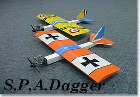
8. We highly recommend putting some bold graphics on the top side of your wing!
9. If you will be landing on rough dry terrain (like we have here in Kansas) you may wish to add spruce or plywood
skids to the forward bottom part of your fuselage.
Flying the Dagger:
1. FOLLOW ALL AMA SAFETY REGULATIONS
2. Install wing with at least 12 #64 rubber bands.
3. Range check your radio.
4. Make sure all control surfaces are set to neutral, and your trims have not been bumped!
5. Make sure your prop is "clocked" to stop horizontal when engine is shut down for
landing.
6. With a properly tuned .40 sized engine running at full throttle, your Dagger will jump into the air with a light
hand launch. DO NOT ATTEMPT THIS BY YOURSELF until your plane has been
test flown and properly trimmed
out!
7. In flight, your Dagger will track like a dagger thrown at your enemy, and if aimed properly, will cut their
streamer clean off for
the kill! There are no bad flight characteristics, and the long fuselage makes it tough
to spin and gives it a great combat "groove". Be ready for a high dead stick glide slope, but
you will be
surprised how well it slows down and flares for landing.
8. Happy hunting!
|