|
Designed for AMA 2610 combat competition, the CoroSpit is our most complex project to date. Although still simple and quick building compared to its balsa wood adversaries, it will require a higher degree of effort and
craftsmanship (as well as patience) than the basic open class gutter pipe planes. We would like to thank Don Fourson of Combat Goblin Models (CGM) for the inspiration to create the CoroSpit. CGM produces the best
2610 Spitfire ARF and kit on the market. It was after building and flying the CGM Spitfire, that we decided to try one with Coroplast®.
This airplane is for experienced builders and pilots! If you are a beginner
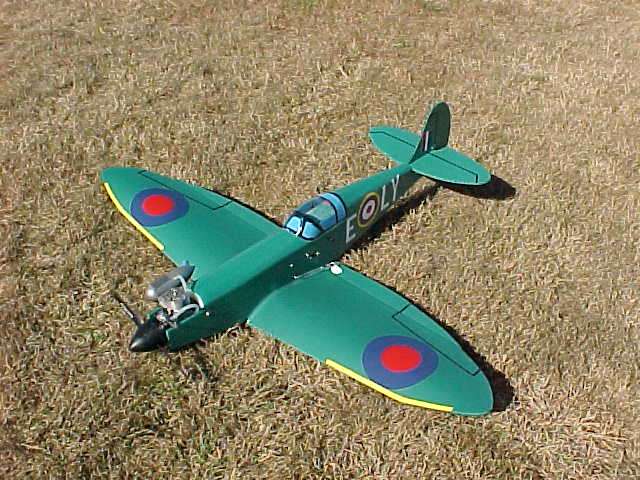
pilot, we do not recommend this airplane at all! If you have never worked with Coroplast®, we strongly recommend building a Derelict or Dominator type airplane before tackling this project. The prototype CoroSpit weighed
all up 2 pounds 7 ounces, and was equipped with a TT® pro .25 engine, a 600ma battery pack, three HS-81 metal geared servos, and 6 ounce fuel tank. It was only seconds into its first flight that we realized we had a real
winner on our hands, and would be putting it down on plans. Please keep in mind while building the CoroSpit that the same ideas and principals presented here can be applied to just about any WW II fighter aircraft which used an
inline engine and a narrow fuselage. Armed with scale 3 view drawings and a little ingenuity
you should be able to create several different WW II fighters.
Materials List:
1. 2 Mil Coroplast®
2. 4 Mil Coroplast®
3. 2 ea. standard wooden yardsticks (wing spar and fuselage joiners)
4. ½ plywood (firewall)
5. 5/32 dowel (for mounting vertical stab)
6. Hardwood for servo rails (and some extra servo screws)
7. ¼ dowel or balsa for elevator pushrod
8. Medium CA
9. Clear silicon sealer for wing to fuselage area and canopy
10. Radio, engine, mount, tank,
tubing, and associated hardware, push rods, clevises etc.
11. Canopy (available from CGM)
12. Propane or butane torch
13. Poster board or other thin cardboard (for templates)
14. Sharp razor knife blades, sharp scissors, and basic hobby tools
15. Clothe pins (to aid in gluing wing tips in place)
Lets go over a few things before you begin building your CoroSpit:
1. The canopy used
on the prototype is available from CGM for $5.00 each and they do take PayPal! Please contact Don Fourson at royfokker@sdf-1.com for more information.
2. Due to the nature of Coroplast® - how it folds, and the
complex shapes of the CoroSpit, extra craftsmanship, and parts shaping will be required to make this airplane come together, please be patient, it will be well worth it. We highly recommend you make your patterns for the
firewall, rear deck former, and vertical stab from cardboard first, and fine trim and fit these cardboard patterns to your airplane BEFORE committing them to plywood or Coroplast®.
3. Building the CoroSpit will rely
heavily on the text in these instructions, so please read them closely!
4. Take your time and use new razor knife blades to cut the complex shapes in the Coroplast®. A good sharp pair of sewing scissors also works very
effectively for cutting the 2 Mil Coroplast® used in wing construction.
5. ALL AREAS TO BE GLUED MUST BE FLASHED PRIOR TO GLUING WITH MEDIUM CA!!! Run a propane or butane torch with moderate flame over the area to be
glued, slow enough to burn the manufacturing oils out of the plastic yet quick enough so as not to burn the plastic! PRACTICE ON SCRAP FIRST! There is very little evidence of the oils burning, however the plastic may warp
slightly and turn a slightly darker color. It will return to normal in seconds. When gluing wood to Coroplast®, a moderate bead of glue may be used. When gluing Coroplast® to Coroplast®, use one moderate drop
every ¼ to ½. USING A BEAD OF GLUE WILL NOT WORK AND IS THE BIGGEST MISTAKE MADE HERE!!! Please be careful in your hobby room of the fire and vapor hazards of flashing and gluing while building model aircraft!
6.
The patterns for the aileron, wing tip, vertical stab, horizontal stab, firewall, and rear deck former are drawn on a 1 grid. Simply measure out and draw a 1 grid on a piece of cardboard, copy the drawings to your cardboard,
and cut out your cardboard templates.
7. If you have any different/better ideas, please dont hesitate to try them! We cant stress this enough! The whole SPAD concept grew out of this attitude! Nothing we do is ever set in
stone! This is especially true in the CoroSpit. In an effort to save the weight of doublers and screws, the wing is glued on permanent, and once the radio is installed from the top, the fuselage is closed up permanently. These
plans will represent this, but you may wish to invent your own method of radio access. Ok
now lets get busy!
Fuselage:
1. The fuselage is laid out on a 30 x 15 piece of 4 Mil Coroplast® with the flutes
running in the 30 direction. Using a straight edge and fine tip marker, lay out the fuselage as shown on the fuselage layout drawing. You will notice several places where the dimension of 4mm is used. Simply use a scrap piece
of Coroplast® (which is 4 mm thick) for this dimension.
2. Using a new VERY sharp razor knife blade and straight edge, cut your fuselage out.
3. Using a straight edge and a small blunt tipped object (such as a #1
Phillips head screwdriver), score and prefold the 4 fuselage bottom fold lines.
4. Using a straight edge and box opener type knife with the blade tip barely exposed, slit the INSIDE FLUTES ONLY of the front and rear decks.
This allows them to curve inward to form the top surfaces of the fuselage.
5. Cut two standard wooden yardsticks down to 7/8 width. This gives you your spar pieces, and the thin sticks will now be used in fuselage
construction.
6. Size and glue the thin yardsticks pieces to both fuselage sides as shown on the left side of the fuselage drawing. Please take extra care in the alignment of the pieces in the firewall area, as a mistake
here could give your CoroSpit an incorrect thrust line, and greatly effect its flight performance. The CoroSpit has NO down or right thrust. Also note that yardstick pieces will need to be shaved down at the rear of the
fuselage to allow proper fit of the lower rear fuselage.
7. Fabricate a Firewall from ½ plywood, and a rear deck former from 2 Mil Coroplast®. This is where craftsmanship, and fine tuning of the patterns comes into
play to make thing fit together well, and give the deck areas the contour you desire. You will also notice that at the forward side of where the rear deck seam comes together, comes to a point. If you are planning to use a
clear canopy, trim this area to give you a nice straight edge.
8. It is highly recommended to drill your firewall for your engine mount, fuel lines, and throttle pushrod at this point
its a lot easier now than after its
installed!
9. Fold up the fuselage, gluing the firewall, and front and rear fuselage bottom sections in place. Do NOT install the rear deck former yet! For extra firewall security if desired, servo screws can be run through
the outside of the fuselage into the firewall.
10. Close up the rear deck by cutting out a ½ wide strip of 2 Mil Coroplast® the length of the seam. When cutting this strip to length, keep in mind that you will want to
leave just enough room at the front of the rear deck for the rear deck former to fit in. Glue half of the strip to the inside of one side, then fold and glue the rear deck together. You may wish to use some masking tape to hold
the rear deck together while the glue dries.
11. Glue the rear deck former inside the fuselage at the front edge of the rear deck.
12. You will not close up the front deck until after the radio gear is installed!
Tail:
1. Using your horizontal stab/elevator template, trace outline to 4 Mil Coroplast® and cut out. Hinge elevator by cutting out the BOTTOM ONLY of the hinge line flute.
2. From a yardstick, cut out the
triangle shaped tail mounting piece and glue into the fuselage, ever so slightly above the Coroplast®. THIS PIECE IS CRITICAL!!! It MUST be glued in solid and level.
3. Glue the horizontal stab/elevator to the
fuselage, making sure it is centered and straight. MAKE SURE THE ELEVATOR HINGE IS NOT OBSTRUCTED IN ANY WAY.
4. Using your vertical stab template, trial fit it to your plane, and make any necessary adjustments to your
pattern before committing it to Coroplast®. Once satisfied, trace to 4 Mil Coroplast® and cut out.
5. Trial fit your vertical stab, and mark horizontal stab for location of a 5/32 dowel which will be installed
into a vertical flute, and into the tail mount wood. Exact location and length of this dowel is not critical, as long as it is in the meat of the stab. Remove vertical stab, and drill horizontal stab and tail mount wood for
dowel.
6. Install vertical stab by sliding into bottom of the fuselage and gluing in place. Install 5/32 dowel down through vertical stab and down into the tail mount wood. Drip CA down flute to glue in place.
Wing:
1. The wing is laid out on a 42 x 19 piece of 2 Mil Coroplast® with the flutes running in the 19 direction. Using your wing tip template, a fine tipped marker and straight edge, layout your wing as shown
on the wing layout drawing, and cut away the areas shaded in lime green on the wing layout drawing.
2. Trace your aileron template to 4 Mil Coroplast® and cut out a RIGHT and a LEFT aileron. Hinge by cutting out the
LOWER SIDE ONLY of the hinge line flute.
3. Fabricate a wing spar with 3 sections of 7/8 wide yardsticks, and glue together with a dihedral brace as shown on the wing drawing.
4. Using a straight edge and small blunt
tipped object (such as a #1 Phillips screwdriver) score and prefold the wing leading edges, tip folds, and dihedral folds.
5. Glue the wing spar to the wing at the lower wing center section, and then one side at a time,
glue the spar to the bottom wing panels.
6. Call your Wife, girlfriend, child, neighbor, or buddy to help you with the next step.
7. One side at a time, trial fold the top wing panel over the spar and against the lower
trailing edge. Mark the inside of the top panel to match the lower trailing edge, and also the top panel wing root must meet the lower panel dihedral fold line. Keep in mind that you are building a low wing that the fuselage
will FIT DOWN INTO, so the gap between the upper panel wing roots must be the same as the fuselage width. While marking the top panels, be sure to hold the leading edge fairly flat (slight raising of the leading edge is
acceptable). Dont worry about the wing tips at this time, simply get the wing roots and trailing edges marked. Well get the wingtips after the top panels are glued in place. Once the above is accomplished, unfold, and
trim the top panels as marked.
8. Glue the ailerons to the lower panel trailing edges. Make sure the hinges are not obstructed and clearly over hang the trailing edge! Note: To help wingtip fit - slit the hinge at the
outboard end (to about a 1/2" in) to allow the Coroplast to "squish" a little so the wingtip looks better.
9. One side at a time, fold and glue the top wing panels to the spar and trailing edge.
10. Trial
fold the wing tips up into the top panels, and mark the inside of the top panels. Trim the top panels for the wing tips. A sharp pair of sewing scissors works most excellent for this!
11. Glue the wing tips in place. Clothes pins work great for this!
Wing Attachment:
1. You must now cut a slot in your fuselage for the wing spar. Measure 2 3/16 back from the lower forward bottom fuselage fold
line and mark. This will be the forward side of your spar slot. Measure the height and width of your wing spar, and mark the fuselage accordingly. Using a sharp razor knife, cut the spar slot in the fuselage.
2. Trial fit your wing to the fuselage, and trim as necessary for a good fit.
3. Glue your wing to your fuselage.
4. Seal the wing root to fuselage area with a bead of clear silicon sealer.
Equipment Installation:
1. Engine , engine mount, and fuel tank are mounted conventionally, and all equipment is installed through the top of the fuselage. Use foam to install your fuel tank as high inside the fuselage
as possible for the best engine performance.
2. Use radio equipment to achieve proper CG. Your CoroSpit MUST balance level to slightly nose heavy AT THE WING SPAR.
3. Use the radio installation drawing as an example for
installing your radio equipment. The drawing represents how the radio was installed in the prototype. Please note that the aileron servo is mounted low (front side on the spar), and the throttle and elevator servo are mounted
high enough to allow the aileron pushrods to run underneath them.
4. The use of hard wood servo rails screwed in place as shown in the drawing assures good solid installation, and greatly aids in the stiffening up of the
fuselage sides. Be sure to GLUE them in place as well as screws.
5. The battery and receiver are wrapped in foam, and can be secured in place with two sided foam mounting tape or (as in the prototype) yardstick scraps glued
in place across the width of the fuselage.
6. Mount the switch as desired. For antenna routing, simply poke a small hole in the left inside fuselage side, and route the antenna down a flute and out the rear of the airplane.
Either use a charging jack on the left side of the fuselage, or simply cut a small slit in the left fuselage side, and poke your charging lead through it.
7. Install control horns to the top side of the ailerons and bottom
left side of the elevator. The prototype used home made horns (made from PVC gutter pipe), and were simply glued in place.
8. Fabricate a conventional elevator pushrod. Please note that a slight Z bend at pushrod exit
points assures freedom of movement. Install all pushrods, cutting approximately 1 ¼ long x I flute wide slots in the fuselage exit points.
9. Rig ailerons and elevator for ½ travel each way (1 TOTAL) and rig throttle for
max, Idle, and CUT-OFF.
10. Double check and triple check all radio installation and operation! The prototype was built to see combat action, so the next time the inside of the fuselage will be seen, will be when picking up
pieces! All servo arm to pushrod connections are Z bends. Also used was a small amount of silicon sealer on the threads of all servo screws to assure they wouldnt loosen.
Final Assembly:
1. Double
check and triple check all radio installation again. When overly satisfied, close up the forward deck in the same manner as you did the rear deck, with a ½ strip of 2 Mil Coroplast®, as well as gluing the front deck to
the top of the firewall.
2. Trim canopy to fit, and glue in place using silicon sealer, or CA.
3. Install a means of combat streamer attachment. The prototype used a small PVC horn glued to the bottom of the fuselage.
4. Add trim decals or stickers. The prototype used home made stickers made from vinyl sign lettering acquired from the same sign supply store where the Coroplast® was purchased. Please note that if you are going to
enter a 2610 combat event, your color and marking scheme must be authentic. With a little leg work in the library or on the internet, Spitfires with all green, blue, and silver schemes can be found. This works out great, as
these are colors the Coroplast® comes in!
Flying:
1. If you are a beginner pilot, and have gotten this far, please do not attempt to fly your CoroSpit without the help of an experienced instructor pilot!!!
2. Follow ALL AMA safety guidelines and regulations!
5. MAKE SURE YOUR PLANE BALANCES LEVEL TO SLIGHTLY NOSE HEAVY AT THE WING SPAR!!! If not, correct the situation before even thinking about flying your plane. A
tail heavy airplane is a safety hazard, and besides, you have put to much work into this to crash now!
6. Make sure your prop is clocked to stop horizontal when the engine is shut off for landing, and make sure that your
radio will shut the engine off.
7. Always have someone else hand launch your airplane for its first flight! Once properly trimmed out, use a slight underhanded upward toss, and your CoroSpit should clime out perfectly in
search of all enemies!
8. Questions? Comments? Please visit the SPAD message board . If you wish to show off your CoroSpit on our SPAD gallery, please send photos to Kraut at collin@spad.org!
|